A Made IT project
http://www.made-it.com
info@made-it.com
| |
A Made IT projecthttp://www.made-it.com info@made-it.com |
The Hewlett Packard answer to 100 Mbps networking and standardized as IEEE 802.12. The name 100VG-AnyLAN explains a lot about the working; the 100 is obvious, but the VG stands for Voice Grade, meaning this network is running on UTP (unshielded twisted pair) category 3 and up. The AnyLAN is meant as being frame compatible with both Ethernet and Tokenring.
Maximum Topology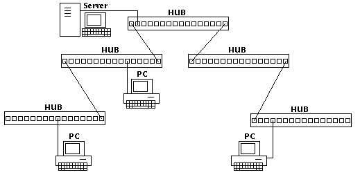
100VG-AnyLAN is a star topology. The maximum amount of repeaters (HUBs) in one network is five. The maximum length of a complete network depends on the cable type used. Cables are discussed below.
Cable types100VG-AnyLAN supports different cable types which all have their own maximum cable length.
| 4-pair UTP cat 3 or 4 | 100 meter |
| 4-pair UTP cat 5 | 200 meter |
| 2-pair STP | 100 meter |
| Duplex fiber 62.5 µ | 2 kilometer |
The IEEE 802.12 defines 100VG-AnyLAN according to the OSI layers, with some additional sublayers, as follows:
| 2 | Data Link | LLC |
| MAC | ||
| 1 | Physical | PMI |
| MII | ||
| PMD | ||
| MDI |
LLC
Identical to IEEE 802.2
MAC
The medium access control is called demand priority and is done by the HUB. This maximizes network efficiency, eliminates network collisions and token rotation delays. The demand priority protocol has another advantage which is that it has two levels of priority for each user request. This makes it possible for time-critical applications such as real-time video to get a guaranteed support.
Demand priority is a methode where the station send a request(demand) to the HUB to send packet across the network. The request has two possible priorities; normal and high. The high-priority is used for time critical applications. Since this is a matter of applications the packet info for high- or normal-priority is already in the packets that the MAC-layer receives.
The HUB scans its ports in a round-robin fasioned way. Each node (station or HUB) may ask to send a packet to the network. A station may if permission is granted send one packet to the HUB, but a lower level HUB may send as many packets as ports available on that HUB, meaning again one packet per station.
The top level HUB (root) is called level 1 and every step down adds a level. This way 3 levels can be made. Each HUB maintains a list of high- and normal-priority requests. All high-priority requests will be serviced before the normal priority requests. Except when there is so much high-priority data that needs to be transported that it would be impossible for a normal-priority packet to get on the network. When this is the case (there is time-out timer that keeps track of that) the normal-priority request is raised to a high-priority request and gets into the same round-robin schedule and is send.
How does a HUB know if the attached node is another HUB or a station. This is done a boot time. The first time the HUB or the node is turned on test packets will be send between HUB and node. This is called Link Training. The HUB and the node test the link, so they know the cabling is ok, the pinning is ok and what kind of device is on the HUB port (bridge, router, HUB, station).
To the packet received from the LLC the MAC-layer adds: node source address, and any required bits to complete the data field. And a FCS (Frame Check Sequence) is added to the end of the packet.
The MII (Medium Independent Interface) and MDI (Medium dependent interface) are just what their names indicate: Interfaces. They do not have any other function than interfacing between the different sublayers so they will be described briefly. The PMI (Physical Medium Independent sublayer) and the PMD (Physical Medium Dependent sublayer) are the sublayers which have the actual function descriptions in them.
A quick overview:
| MAC | MAC Frame | |||
| PMI | Scrambler 0 | Scrambler 1 | Scrambler 2 | Scrambler 3 |
| 5B6B Encoder | 5B6B Encoder | 5B6B Encoder | 5B6B Encoder | |
| MMI | Preamble, Start Frame, End Frame Delimiter | |||
| PMD | Two-Level NRZ Encoder | Two-Level NRZ Encoder | Two-Level NRZ Encoder | Two-Level NRZ Encoder |
| Transmit Pair 1/2 | Transmit Pair 3/6 | Transmit Pair 4/5 | Transmit Pair 7/8 | |
| Channel 0 | Channel 1 | Channel 2 | Channel 3 | |
The PMI takes the MAC frame octets and devides it into 5 bit quintets which are feed to a scrambler. Each quintet represents a pair on the UTP cable (4 pairs) for 2 wire fiber or 2 pair UTP 100VG-Anylan uses a multiplexing scheme.
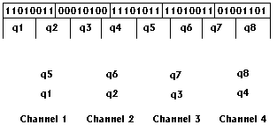
The scrambler scrambles the 5 bit quintets in such away that radio frequency interference and signal crosstalk are reduced to a minimum.
After that a 5B6B encoding scheme is responsible for putting the 5 bit quintets into 6 bit symbols. This way a balanced data patern is created containing equal amounts of 1s and 0s. Since there are only 16 balanced symbols available, 16 data paterns require two 6 bit symbols. The reason for this is clock synchronization for the receiver circuitry, and it adds an easy way for error checking.
The MII adds a preample, start frame delimiter and end frame delimiter. Everything is now ready for transmission.
PMDThe main functions from the PMD are channel multiplexing if needed and NRZ encoding.
NRZ (NonReturn to Zero) is a two-level signaling mechanism. Per clock cycle one bit is transmitted, where a low voltage represents a 0 and a high voltage an 1. An example for 4 pair UTP is given below:
| Bit Value | 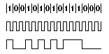 |
| 30 MHz Clock | |
| NRZ Encoded Data |
For UTP a RJ45 connector is used and for fiber all kinds of fiber connectors are available.
| Male | Female | |
|---|---|---|
| RJ45 |  |
 |
| Male | Female | Side | |
|---|---|---|---|
| ST |  |
 |
 |
| SC |  |
 |
 |
| SMA905 |  |
 |
 |
| SMA906 |  |
 |
 |