
A Made IT project
http://www.made-it.com
info@made-it.com
| |
A Made IT projecthttp://www.made-it.com info@made-it.com |
Introduction
More and more fiber cables are installed and more and more confusion arises. This document is meant to take a way the mystics around fibers. To do so let us first look at a fiber cable and define the different parts of it:
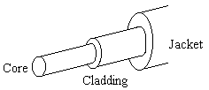
A fiber cable is built up of a jacket, usually PVCor rubber, and the actual fiber. The actual fiber consists of two pieces of fiber. One is called the core and the other is the cladding. The core is the propagation path for light and the cladding, which has a different density then the core, acts as the refractive layer. The light that tries to escape the core is reflected by the cladding so the light stays in the core.
There are two types of fiber cables:
Multimode fiber
Mainly used for short or medium distances and for applications requiring a low bandwidth. The sizes used (the first number is the core diameter the second is diameter of the cladding):
Single mode fiber
Mainly used for long distances and for applications requiring a high bandwidth. The sizes used (the first number is the core diameter the second is diameter of the cladding):
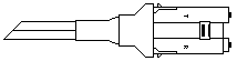
Connectors
Here are just a couple of connectors that are available for fiber:
| Description | Male | Female | Side View |
|---|---|---|---|
| SMA905 |  |
 |
 |
| SMA906 |  |
 |
 |
| ST |  |
 |
 |
| MIC |  |
 |
 |
Light Sources
As mentioned before there are two different light sources:
Link Budget
The most difficult thing about fiber seems to be the calculation of a fiber budget. The transmitter transmits a certain amount of light and the receiver needs a certain amount of light to understand what is send. The difference between the two is the link budget. The amount of light a receiver needs to understand the data is called the receiver sensitivity.
The optical power is mostly given in dBm, which is calculated as follows:
Power [dBm] = 10log (Power [mW] / 1mW)
Most ideal would be if you were able to measure the power at the beginning (Pin) and ending of the cable (Pout). To calculate the loss would then be:
If measured in mW: loss [dBm] = 10log (Pin / Pout)
If measured in dBm: Loss [dBm]= Pin - Pout
Most of the time the cable loss is given and you know what your devices are doing and you want to know how much distance you can cover. Or you know the distance and you want to know the type of cable to use. The formula, with all numbers in dB:
Output power - total cable loss - total connector loss - total splice loss - 3 dB >= Receive sensitivity
To give you some idea of the numbers associated with the words:
| Cable Loss | |||
|---|---|---|---|
| 850 nm | 1300 nm | 1550 | |
| 50/125 µm | 3.0 - 3.5 dB/km | ||
| 62.5/125 µm | 3.5 - 4.0 dB/km | 1.0 dB/km | |
| 100/140 µm | 4.5 - 6.0 dB/km | ||
| 9.5/125 µm | 0.4 - 0.5 dB/km | 0.25 - 0.3 dB/km |
| Connector Loss | |
|---|---|
| SMA | 0.5 - 3 dB |
| ST | 0.5 - 1.5 dB |
| FC | 0.5 - 1 dB |
| MIC | 0.5 - 1 dB |
| SC | 0.5 - 1 dB |
A splice is a the way two fibers are coupled to make one long one (NOT a coupler). A splice introduces about 0.1 - 0.3 dB.
The 3 dB loss is a general "spare" loss to compensate for the aging of the used components and to compenstate for temperature differences.