A Made IT project
http://www.made-it.com
info@made-it.com
 |
A Made IT projecthttp://www.made-it.com info@made-it.com |
Why this document
The reason for writing this document is not completing the database, but the confusion that rose while supporting ISDN (related) problems. The way this document is written is due to these problems, so this document won't be complete and may not even be accurate, all though we do our best. Please give us your input to make it better.
General
ISDN as the name implies is a digital service which is offered by the local Telcos to replace the POTS (Plain Old Telephone Systems = analog telephones). ISDN has two flavours, Basic Rate Interface (BRI) and Primary Rate Interface (PRI). Every interface is built up of n times a B-channel and one D-channel. The B-channel is used for the actual dataflow and the D-channel is used for the setup and clearance of a call and for error and message handling needed during the call. Now the confusion starts, because there is a European version and a US version with different speeds. To give a quick overview:
| European | US | |
|---|---|---|
| B for BRI | 64 kbsp | 56 kbps or 64 kbps |
| D for BRI | 16 kbps | 16 kbps |
| B for PRI | 64 kbsp | ??? kbps |
| D for PRI | 64 kbps | ??? kbps |
The BRI consists of 2 B-channels and one D-channel (where the D-channel is 16 kbps) and PRI is 30 B-channels and one D-channel (where the D-channel is 64 kbps).
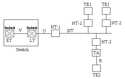
Since ISDN is a digital network it tries to comply to the ISOs OSI-model. The higher level you take in the OSI model the more differences you will find in the protocols. Let's start of with a general picture of how an ISDN network looks like:

The switches are part of the telco network from which the U-interface enters the customer premisis. Most US telcos leave it to that, where the European telcos do supply the NT-1 (Network Termination unit 1) and leave the customer with the S/T interface, also called S-bus or S0-bus.
The U-interface
The U-interface is a two wire (single pair), full-duplex interface with a 2B1Q line encoding. This means that the transmit and receive signals run through each other. This interface supports one unit which has to be a NT-1.
The S/T-interface
The S/T-interface is normally called the S-bus or S0-bus and complies to I.430 ITU-T. This consists of four wires (two pairs), where one pair is used for transmit and one pair is used for receive. The connectors used are RJ45 (8 wire) where only the middle pairs are used. On one S-bus you could connect 8 devices (the NT-1 not included).
When one devices is connected to the S-bus the max. cable run is 1 km. For 8 devices this distance is limited to 150 meters. The placing of the NT-1 does not influence this since the NT-1 could be placed everywhere on the cable (begin, middle, end).
|
|
|
This interface supports up to 7 devices which all have to be NT-2s.
The R-interface
The POTS interface.
ET
The ET (Exchange Termination) is the switch that connects the local ISDN line to all other switches in the network.
LT
The LT (Line Termination) is the local loop switch, which connects the U-interface to the ISDN cload of the Telco through a V interface.
NT-1
The NT-1 is the Network Termination unit 1 and is a customer premesis unit. The NT-1 converts the single pair U-interface to a four wire S-bus and supplies, through an external power source, the power to the connected ISDN devices. The power provided by the telco is enough to power one ISDN device on the S-bus in case of a power down. All other devices are power locally by the NT-1
NT-2
The NT-2 is the Network Termination unit 2. You will probably not find this unit in any ISDN network because this unit is integrated into the ISDN device called TE1 or TA. Officially this interface converts the T-interface of the bus into a S-interface, which are electrically equivalent. The NT-2 handles the layer 2 and 3 protocols.
TE1
The TE1 (Terminal Equipment) is an ISDN device. Like an ISDN-telephone, fax, bridge, router. These units have an ISDN interface (RJ45).
TA
A TA (Terminal Adapter) is an unit that provides the interface between a non-ISDN device and the ISDN S/T-interface.
More indepth description
This section contains:
Layer 1
Now we run into problems. We have several different interfaces, so what is Layer 1, well we have a S-layer-1, an U-layer-1, a R-layer-1 and a V-layer-1 and ofcourse BRI and PRI. Nice isn't it? And yes there is an European and an US version!
The R-interface is out of the scope of this document since that handles analog telephone lines.
Let's first devide BRI and PRI. For PRI you will probably get an E1-line with a G.703 interface. But check with your local telco. PRI is a subject we still need to work on.
The U-interface for BRI
The U-interface for BRI is 2-wire (one pair) copper cable with a capability of 160 kbps (144 kbps (2*B + D) + 16 kbps for frame overhead, like error handling). Transmit and receive signals travel over the same lines at the same time. Echo cancellation is used to reduce noise. The encoding schemes used are:
2B1Q for the US and 4BT3 for Europe.
The Frame Format:
The total U-interface frame consists of 240 bits which looks like:
| SYNC: 18 bits | 12 times (B1 + B2 + D): 216 bits | Maintenance: 6 bits |
The S/T-interface for BRI
[META]
The Frame Format:
[META]
Layer 2
The Data Link Layer or Layer 2 of the OSI model describes the way a link is setup and maintained together with Layer 3. The protocol description is thus specific for the D-channel.
The different protocols:
Layer 3
[META]
Bonding
Bonding is an ISDN protocol that allows for up to 31 B-channels to be 'bonded' to one huge datachannel to support speeds over 64k. The incoming high-speed datastream is split into various 64k channels, transported over the ISDN, and then the separate channels are combined again. The problem that has to be overcome is synchronization, since the different 64k pipes are not all travelling the same route.
Mode 0 - provides initial parameter negotiation and Directory Number exchange over the master channel, then reverts to data transmission without delay equalization. the daley equalization is performed by some other means (e.g. an attached video codec).
Mode 1 - supports user data rates that are multiples of the bearer rate. It provides the user data rate with full available bandwidth, but does not provide an in-band monitoring function. The overhead octets are removed after the call is phase alligned. Error conditions that disrupt overall synchronization are not recognized automatically. Recovery from these eror conditions requires manual intervention.
Mode 2 - supports user rates that are 63/64 of the bearer rate. It provides an in-band monitor function, but does not use an extra channel to replace the overhead octets required for monitoring.
Mode 3 - supports user rates that are an integral multiple of 8kbps, including N x 56kbps and N x 64kbps. An in-band monitoring function provides a continuous check for delay equalization and an end-to-end bit error rate test. The overhead octets required for monitoring are providing by adding bandwidth (most likely an additional bearer channel) thereby preserving the full user data rate.
Mode 1 is the common mode of operation for all BONDING compatible implementations.