
A Made IT project
http://www.made-it.com
info@made-it.com
| |
A Made IT projecthttp://www.made-it.com info@made-it.com |
The reason
The idea of switching on layer 3 was first proposed by a company called Ipsilon. Different standards emerged and at the moment of writing this document there is still no definitive standard. There are some solutions though that are incorporated in a standard (like ATM). For detailed descriptions see the vendors Web-Sites mentioned.
The problems, or network history in an eye-wink
Before looking at the solutions it is good to see what is causing the problems.
First, when networks emerged there was a need to extend the maximum distances, so repeaters were invented. After that, people wanted to connect LANs over Wide Area Networks (WANs). This problem was solved by building bridges. When more and more networks were linked together routers were needed to make the whole thing managable.
And when we had that we wanted more speed. More speed meant creating switches. The first were just called switches and switched on OSI layer 2, so they were actually switching bridges and now we need more speed and have real time traffic and need 3rd layer switches, which are actually switched routers.
But since a router is situated on layer 3 it adds delay and there is another problem with routers, they route. This means that data can follow different routes to their destination with as a result that some packages will arrive earlier than packedges send before them. This makes it impossible to run time sensitive applications.
The solutions
The problems that need to be solved is the different routes for packages from the same job and the delay added by the routers.
Solving different routes seems to be the easiest one. Just take a fixed path and the problem is solved, but implementing this is the real problem.
Solving the delay factor, once there is a fixed path, is actually a piece of cake, because with a fixed path bridging is all that is needed.
The propositions for call setup
The solution for a fixed path is a call setup, where there is a detection of the destination and an agreement on the path that is used for the time the link is used. The technics used sound like ATM and that is were everyone agrees on; ATM will be the future. But in the meantime we have an installed base of several thousands of routers which are connected through dedicated lines and no ATM. So there is a need for a temporary different solution.
Let's see what the posibilities are on the 3rd and 2nd layer of the OSI reference model:
| Layer 3 | Route everywhere |
|---|---|
| Route once, switch afterwards | |
| Layer 2/3 | Switch here you can, route where you must |
| Layer 2 | Switch everywhere |
The first option, route everywhere, is the actual router as we know it today. And the last one, switch everywhere, is a real bridge. So those two options are not our concern in this document.
Route once, switch afterwards VS Switch where you can, route where you must
Those two options have a basic different view of the network. The switch where you can device sees the network as being flat and is mainly a bridge. Only when it isn't able to determine where the data must go it will use it routing capabilities.
The otherone is mainly concerned about routing. It accepts the network as a must route network. Only when it has the knowledge of the path the data ought to go it will switch.
Later on we will see the importance of those two different views of the network.
The technologies
The now known architectures can basically be split up into three different functions:
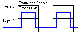 |
The Conventional Router |
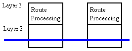 |
The Routing Switch |
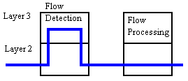 |
The Flow switch |
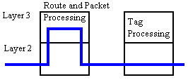 |
The Switched router |
None of the above are a world wide standard and none are interchange able with another.
For a more close description on the different schemes please contact the vendors and read the specs given with a certain product carefully!!!